EasyShop
a robotic grocery vending machine
Rebecca Shen
Stephanie Bentley
Taylor Korte
Daniel Ryaboshapka
Moises Abbo
For our Senior Design Capstone project (Fall'21), my group and I were presented with the challenge, "make grocery shopping easier, " by our sponsors Amazon Robotics.
our solution:


project highlights
A user can interact with our UI hosted on a web server (shown in the demo video) and select what kind and the quantity of produce they want.
click through!
discovery &
planning
demo video
how it works
The main mechanical components of our design:
(1) a xz plotter & linear actuator assembly that give our end effector 4 degrees of freedom and (2) a T-slot frame housing gravity assisted shelves and product bins
mechanical design


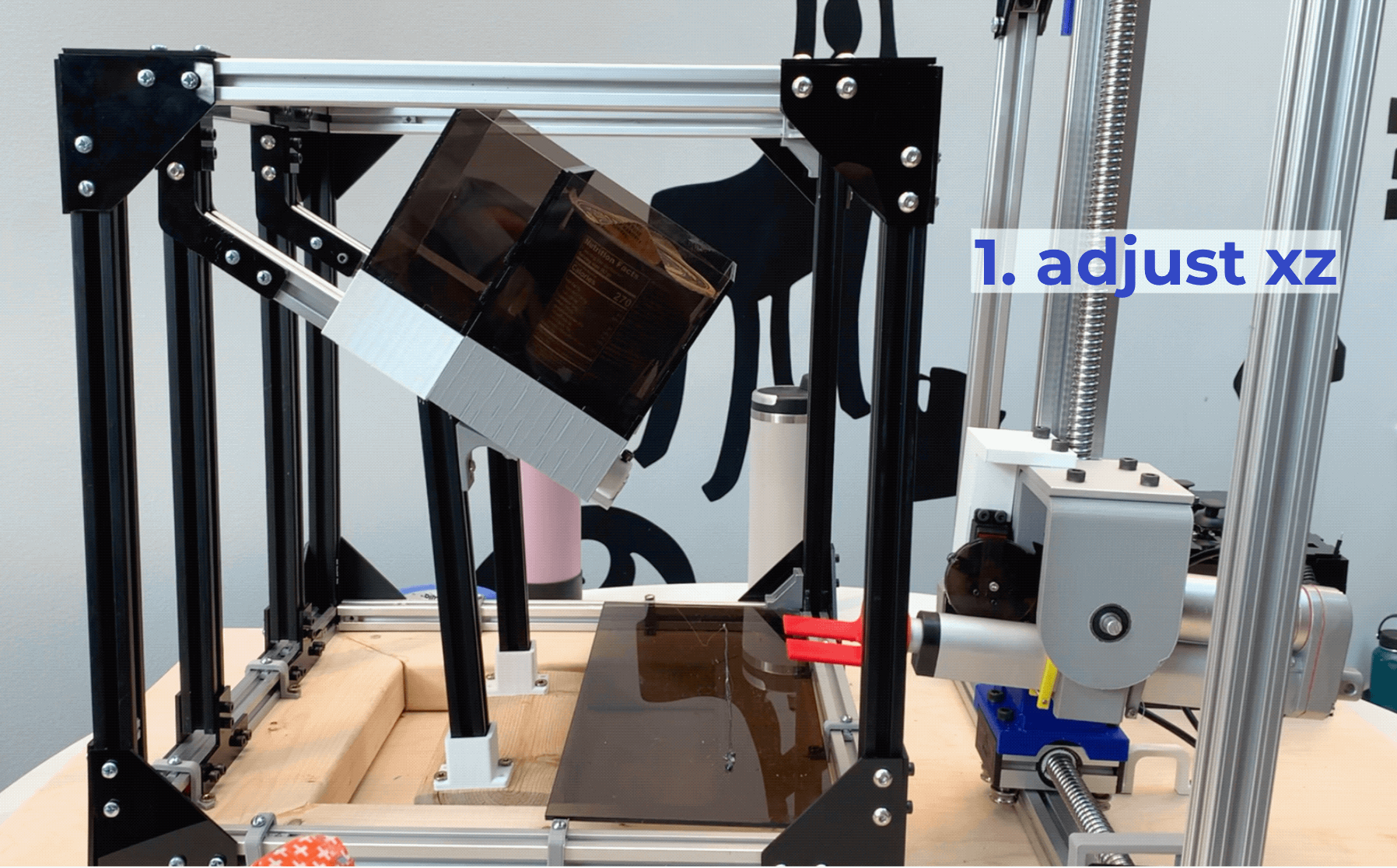
The xz plotter then positions the entire end effector assembly in line with one of the shelves. A servo motor rotates the assembly to make the prongs aligned with the shelf of choice, and then a linear actuator extends the end effector until it slots into a bin base. The actuator then lifts, retracts, lowers, and gently pushes the bin off, successfully vending the item.
my contributions
I worked with Taylor and Stephanie on the mechanical design of the vending machine, mainly the xz plotter, parts of the linear actuator assembly, and bits of the T-slot shelf/bin system.
To the left are a few key parts I designed!


How can we make grocery shopping easier?
This is the question we first started out with. Our initial brainstorming sessions were full of ideas, but it ultimately boiled down to- what can we design to help people?
An initial meeting with our sponsors gave us these parameters to build off of: the product should be a commercial robot, helpful, COVID-safe, & different than the current solution (scanner + grocery cart).
product discovery
Before we could start ideating, it was important to get a better sense of what the current market was like and of existing solutions. We split up research into: hardware, software, existing solutions & competition, and materials.
Since we were working with a robotics company, it was safe to assume that some of our potential solutions would include some classic robotics components, like an end effector, arm, moving platform, etc. We focused on researching current robotic solutions, and identifying what we liked and disliked about each.
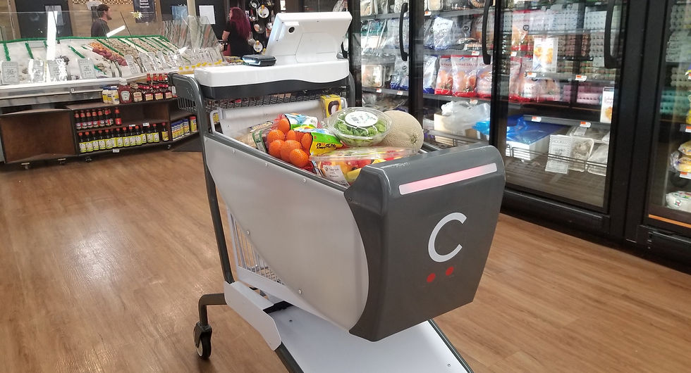
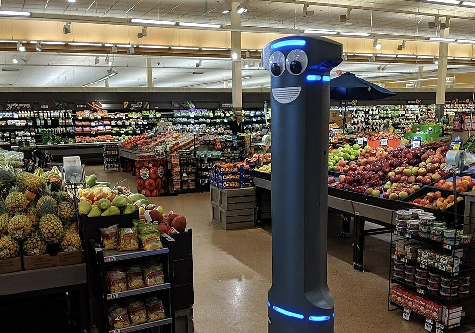
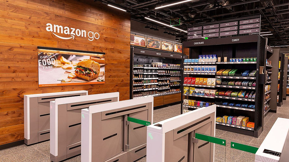
current solutions
The slideshow above shows three solutions that helped us better understand the scope of our problem & solution.
gantt chart

product definition
Even with the amount of research that we had done, we knew our problem statement still needed refining. We really needed to dive deep and consider all aspects of grocery shopping, especially the key stakeholders and our intended consumer audience.
Our House of Quality kicked off our set-based iteration journey, leading to productive discussions about what exactly our user and engineering requirements should be.
house of quality

A key realization we had from completing the HoQ was how broad our current problem statement was. Grocery shopping affects most of the population, and while it was extremely helpful better understanding the impact our solution could have, it meant we needed to do a lot more design iteration to get to our minimum viable product.
TED Talk I
The main takeaway from this initial research phase + HoQ was our first problem statement iteration, as presented in TED Talk I.
new PS:
Is there a low-cost, fast, and accurate method to automate in-store grocery shopping?
TED Talk I was our first experience pitching ideas as a group to an even larger group of people, teaching us how to give concise, convincing presentations, which is something we continued working on throughout the semester.
concept design
set-based design flowchart

Now that we had a new problem statement, it was time to begin set-based iterative design.
The general concept behind Set-Based Design is to start with a large set of ideas and narrow them down over 3 iterations (A, B, C). This would give us a solution with better design outcomes, better integration of ideas by stakeholders, and a cost-efficient yet detailed design.
set A design:
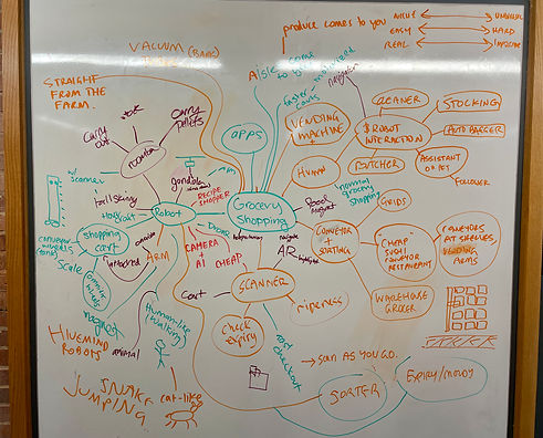
For Set A, we met in Nolop and did a concept generation brainstorming sprint, resulting in a mindmap with "grocery shopping" at the center. The goal of this session was to stay as general as possible in order to generate the broadest range of ideas. Throughout this process, we kindly reminded each other to not fixate on a single solution, leading to a mindmap full of ideas.
We also took into mind the brainstorming session we had done in class using 3 scales:
(1) Niche -> Universal
(2) Easy -> Hard
(3) Real -> Impossible
We went through all of the ideas on the board and rated each one on all 3 scales, giving us a better sense of what was actually feasible for this semester.
set A mindmap
set B design:
To help us refine our ideas and get us to Set B, we decided to utilize the Nolop whiteboards again. From our House of Quality and our Set A brainstorming session, we took more specified user-requirements and each grabbed a marker.
This was a very useful exercise as it helped us start visualizing possible solutions. Our previous Set A mind map left us with so many ideas, and this morphology chart let us start combining those ideas with the requirements we hoped to include in our design.

set A->B morphology chart
Our meeting with the Bray staff was during our Set B generation phase. This was helpful in understanding the physical feasibility of our solution, and also helped us reach Set C. During our meeting, we came to another realization that our problem statement was still too broad, which we had gotten a sense of from the breadth of ideas we were discussing. Therefore, we decided to iterate our problem statement once again.
set B mindmap

How can we reduce the difficulty of stocking/picking grocery items in an aisle?
This new problem statement also modified our target consumer audience to people who experience difficulty retrieving or stocking items in a grocery store aisle, whether that be from physical ability or COVID-19.
We then went back to the Nolop whiteboards and created a new mindmap, giving us more specific solutions that would launch us into Set C.
set C design:
Our Set B Mindmap gave us 5 ideas:
(1) Attachable Arm (Rebecca)
(2) XY Plotter (Dan)
(3) Wire System (Stephanie)
(4) Vending Machine (Taylor)
(5) Free-Standing Robot (Moises)
The carousel below shows renders of each solution, which we presented to our sponsors over Zoom. Click through all 5 and give a picture an extra click to learn more!
 |  |  |
|---|---|---|
 |  |
set C renders
set C to final design:
Our meeting with our sponsors gave us some valuable feedback that we took into account when choosing our final design. Although we loved so many of ideas, especially the wire system, we were advised to pick something that would feasibly let us develop a minimum viable product. To aid us with the decision, we did a group ranking system, as well as a Pugh chart. This let us choose a design that would both be feasible and true to the requirements we had wanted to meet since the beginning.
pugh chart

Vending Machine
final solution:
development & prototyping
Our first steps after deciding on a final design were to revisit the CAD model Taylor had made and see what changes we could make to (1) incorporate what we liked about other designs & (2) make it fit our $400 budget.
We decided on the following mechanical design:
(1) A vending machine shelving + bin frame made out of T-slots to minimize costs
(2) A xz plotter with an attached linear actuator, creating 3 DoF
(3) A linear actuator assembly with an end effector at the end of the actuator & a servo motor that can rotate the actuator + end effector, creating 1 more DoF
We decided to us a gravity assisted shelf design to reduce costs and avoid having to automate everything. The animation below details the entire vending process.
We ended up fabricating a lot of parts. Here is an exploded view that has 1 of everything we made + the parts we bought.

cad
Taylor, Stephanie, and I spent the next few days CADding and rapid prototyping using the 3D printers, laser cutter & various machinery at Bray.
designing the xz plotter
We used 2 ball screw linear actuator assemblies for the XZ plotter as they would be too time-consuming to make ourselves. These were the most expensive components in our system, and after some research, we chose a 300 mm length one driven by a NEMA 17 stepper motor.
Since we were using 2 stepper motors, we needed several A4988 drivers.
To attach the Z-direction screw assembly to the X-direction one, I designed & 3D-printed a stepper motor mount that press fit and screwed into both assemblies


final design
initial design
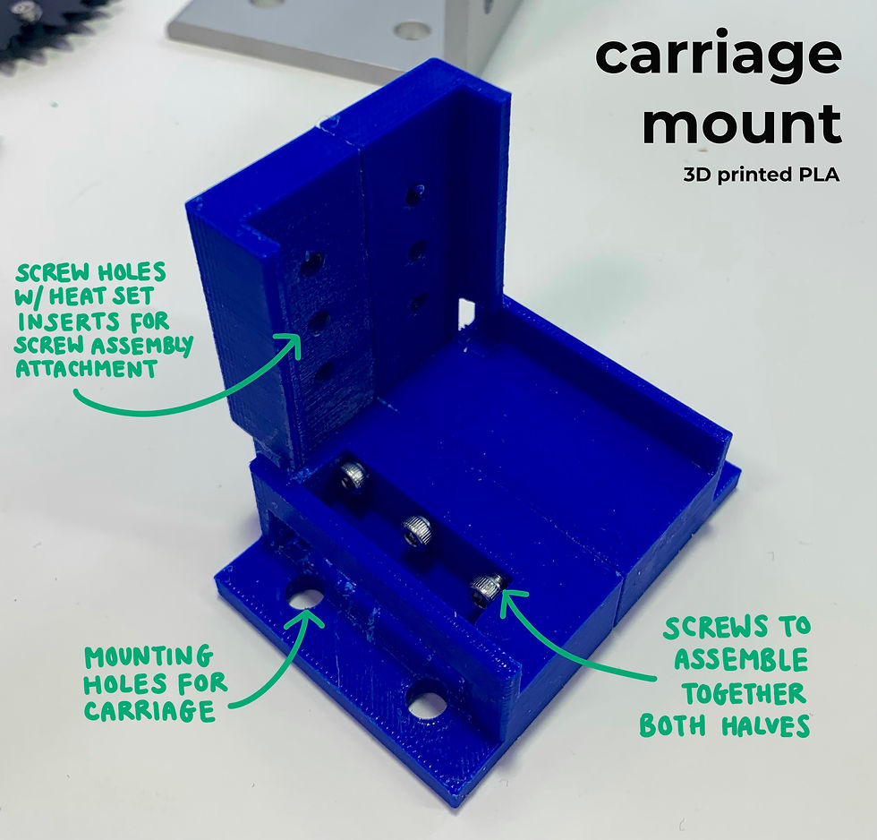
We needed the Z screw assembly to attach to a T-slot frame for extra support. I designed an attachment made of 2 pieces that screwed together and onto the back of the assembly. I also designed a carriage, and while it fit into the T-slot, there was too much friction. I incorporated heat set inserts into this design so I would not over-thread the PLA and to create an overall stronger attachment. However, as you can tell by the screws poking out, I learned the hard way that you should CAD holes slightly smaller than the insert size, not a lot smaller like I did.
For the final design, we decided to use our remaining budget to purchase a carriage which ran much smoother on the T-slot. This required some redesign, and with some test prints to check the tolerances, I was able to produce a carriage mount that fit extremely well.
initial assembly


final assembly
Here is our first proof of concept prototype- a working XZ plotter. The initial motor mount fit quite well around the stepper, but was too loose around the bottom screw assembly.
These two photos show the final XZ assembly a little better. I re-printed the motor mount to have a higher infill (making it stronger since it needed to support a lot of weight) & with better tolerances, creating a tight press fit.
Here is a slideshow of each part I designed along with the engineering drawing.
designs + engineering drawings


designing the linear actuator assembly
This was probably the most challenging assembly to design.
We used a 6 in linear actuator we got off Amazon that was reliable but very heavy.
We borrowed a metal L bracket from Brandon Stafford & a continuous metal geared servo from Milan Dahal.
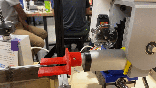
Since the linear actuator had no easy way of being attached to the Z screw assembly, we had to devise an assembly to solve that problem. Here is another Nolop whiteboard sketch of our initial design ideas, and we decided hang the linear actuator from a L-bracket attached to the screw assembly. From that bracket, a brace with a metal rod going through it supports the linear actuator, which rotates using the servo motor and a gear system aimed to increase torque.
I designed the gear system and the animation below shows how the system rotates.

final design + engineering drawings

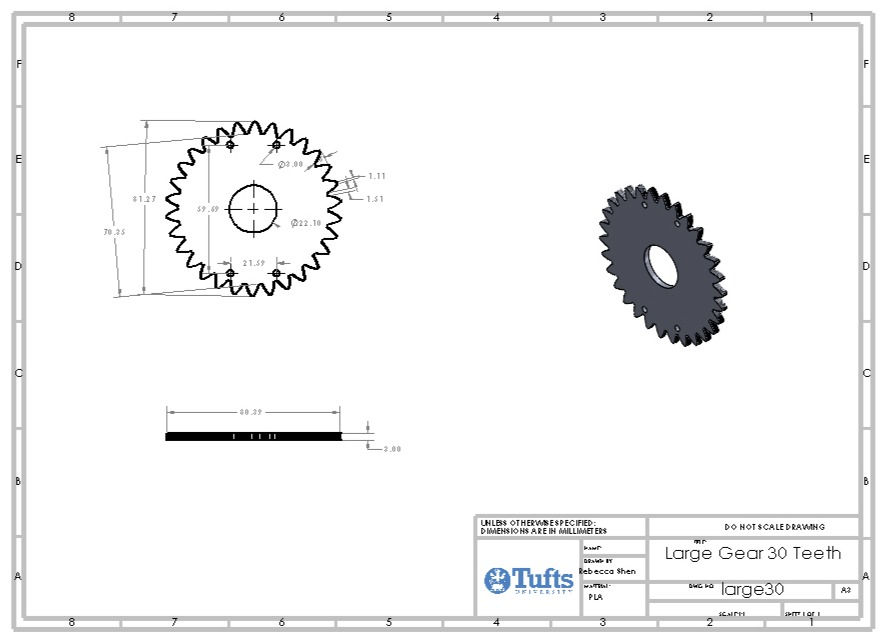

The gears took quite a bit of iteration since they were incorporated towards the latter half of the design. Although it is quite simple, they help shift the torque from the linear actuator so that it is not directly on the servo horn. Since the servo had metal gears and also a metal horn, we were confident it could support the weight of the system, but the gears would be helpful as well.
I used a 3:1 gear ratio and mounted the larger gear to the linear actuator mount. The small gear was attached to the servo using several small screws. 2 acrylic circular plates sandwiched the small gear and part of the large gear to prevent out of plane slipping. We had to reinforce the servo motor mount to prevent un-meshing of the gears & after several iterations, we made it work.
assembling everything
Assembly took several days, lots of last minute re-iterating & designing, and lots and lots of screws.
frame day 1

xz plotter gets a top rail

frame day 2

frame day 3
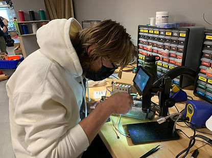
soldering & heat shrink
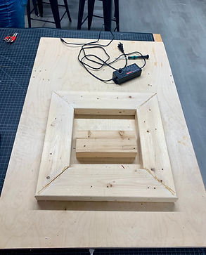
wooden base
final design
final setup

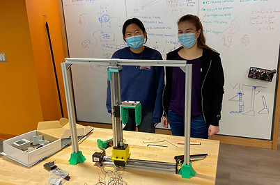
my team!


By demo day, we had a working vending machine that:
-
accepted user orders through a web server hosted UI
-
had a scalable & modular design
-
had a automated xz plotter + end effector assembly to vend the user's order
code & software
Dan wrote all the code for the system + the web server UI.
There were 2 microcontrollers use: a Raspberry Pi 4 + an Arduino. Serial UART communication was set up between the two. For the UI, a Flask server was used with a JavaScript frontend that stored the inventory & shopping cart.
2 modes of control:
(1) autonomous - the vending machine gets sent the order and locates the item on its own
(2) manual - a user can manipulate 2 joysticks (1 for the xz plotter, 1 for the linear actuator)
Moises created a UI with a greater selection of produce + a "call for help" function that we hope to utilize in future iterations.

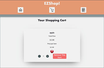
UI
joystick control
reflections
Working on this Senior Design Project was a great learning experience: both in mechanical design & in the engineering design process.
engineering design process
We were able to go through the engineering design process very thoroughly, and I enjoyed how in depth we went. It was nice being able to be presented a broad problem and then really choosing what path we wanted to take. I think the time spent iterating helped us achieve a good minimum viable product.
prototyping & designing
I loved how hands-on this project was and how much I was able to test & redesign. Especially for such a big system, it meant that I had to learn how to design with others and get my components to interface well with theirs. Also, heat set inserts are the best!
other lessons learned
Here are my key takeaways:
(1) Design for a minimum viable product but leave room to expand if you have time to
(2) Design for modularity & flexibility
(3) Dimension & define all of your SolidWorks models
(4) Do not be afraid to ask other classmates or professors for advice/help!
future iterations
(1) Acquire faster/better linear actuator
(2) Put limit switches/sensors everywhere
(3) Build another T-slot frame & stack it on top
(4) See if it is possible to build own screw assembly
(5) Test with heavier objects